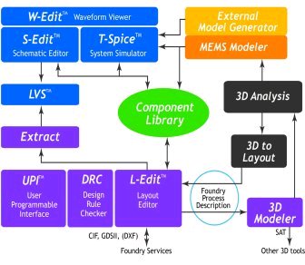
MEMS Pro v6.0 is a flexible, powerful, easy-to-use CAD tool suite for the design and analysis of micro-electro-mechanical systems (MEMS). It offers an integrated solution for the design process that shortens development time while providing designers reliable analysis for manufacture. Functionalities include mixed MEMS/IC schematic capture and simulation, full custom mask layout capability and verification, 3D model generation and visualization, behavioral model creation and links to 3D analysis packages.
Try MEMS Pro v6.0 for 30 Days
Download the DATA SHEET and CONFIGURATIONS document in .pdf format.
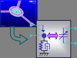
Modeling Tools: MEMS Modeler automatically generates behavioral models ready for system simulation with electronics and packaging from 3D data from analysis packages. Complex, finite element models involving a large number of degrees of freedom are reduced to a few master degrees of freedom. Users can also create their own models from analytical equations and the tool generates simulation-ready descriptions in a variety of popular formats.
Layout
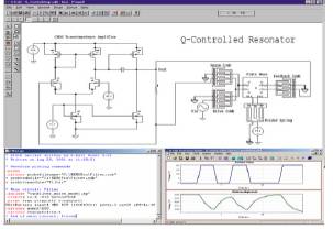
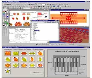
Editing: MEMS Pro v6.0’s
physical design environment includes a fully hierarchical and full
custom editor engineered for MEMS and IC design. The program uses an
intuitive interface and provides specific MEMS-related capabilities
that greatly reduce layout time. It provides all-angle support. A curve
generator allows designers to create MEMS primitives, such as torii,
splines, fillets and general equation-based curves. The EasyMEMS tool helps to
automate tasks that are time-consuming for creating MEMS mask layout
such as creating polar arrays. Useful macros include the generation of
holes and dimples to properly release MEMS structures. A
powerful interface is included for automating, customizing and
extending the layout editor command and function set using the C
language. Popular output formats are supported so mask designs are
“foundry ready”.
MEMS
Verification provides
a configurable design rule checker that verifies MEMS layout against
fabrication requirements to prevent costly design errors causing extra
fabrication runs and ensures manufacturability. In addition,
application and device specific context sensitive rule
checking is included. An Extractor generates a SPICE netlist
from a MEMS layout including MEMS devices, their parameters and
multi-domain connectivity. The LVS (Layout vs. Schematic) tool
takes the extracted data and compares it against the SPICE netlist from
the schematic editor to ensure that the mask layout captures the
designer’s intent.
The 3D Solid Modeler creates a 3D view of a MEMS device from the device layout and
fabrication process description. An easy to use GUI permits designers
to enter fabrication process steps and sequences. Surface and bulk
micromachining process steps such as material deposit, etch, mechanical
polish, diffusion, growth, electroplating and wafer manipulation steps
are supported. The 3D model may be scaled and a subset of mask layers
may be selected for view. Models can be viewed with rotations, zooms,
and preset views. The Cross
Section Viewer displays a cutaway view in the z-dimension
based on a user-specified cut line. As MEMS are inherently 3D
structures use of these tools is important to understand the resulting
fabricated device structure in 3D dimensions. 3D-To-Layout converts
3D solid models into 2D mask layouts using user-specified fabrication
process descriptions, enabling capture of device mask modifications
made in 3D analysis programs.
Foundry Modules enable targeting of specific process technologies and provide process-specific device intellectual property. A variety of foundry-specific modules are fully integrated with SoftMEMS’ tool suites to ensure process compatibility and manufacturability with the world’s leading MEMS foundries. Foundry modules include design rules, mask layer descriptions, device descriptions for extraction, process parameters and material properties, and fabrication process descriptions.